CAD Drafting & 2D Modeling

We provide a full-cycle production of technical 2D and 3D deliverables based on point clouds and/or other geospatial data. We develop elevation and section drawings, Digital Terrain Models (DTM), Topographic Plans (Site Plans), Cross Sections, and other drawing outputs ready for integration into CAD, GIS, or CAFM environments.
Our CAD deliverables support refurbishment and reconstruction projects, design engineering for utility and transport infrastructure, urban planning, asset digitization, and the implementation of CAFM solutions.
We ensure compliance with international standards, technical accuracy, and client-specific formatting.
Areas
We ensure compliance with international standards, technical accuracy, and client-specific formatting.

Case Studies

Exceptional results in complex projects

Topographic Plans (1:200) for 95 Railway Level Crossings

Archizem completed the topographic and geodetic data processing and produced 95 individual topographic plans at a scale of 1:200 for railway level crossings. Each plan details the transport and engineering infrastructure, along with surrounding features, within the defined project area for every location.
SEE DETAILS

Topographic Plan (1:200) for Railway Infrastructure Reconstruction

Archizem completed the office processing of topographic and geodetic data and produced a detailed topographic plan at a scale of 1:200 for a railway corridor approximately 4.75 km long and up to 60 m wide. The plan captures all railway and engineering infrastructure elements, as well as adjacent areas, within the project scope.
SEE DETAILS

Services

01

CAFM Drawings

We specialize in creating precise layout drawings of buildings and premises based on laser scanning data (point clouds), specifically optimized for seamless integration into Computer-Aided Facility Management (CAFM) systems. Every object on the drawing – a room, zone, or engineering element – receives a unique identifier and a set of attributes: precise area (usable, gross floor area, according to DIN 277), height, purpose, finishing materials. All information is structured into logical tables and semantic layers, strictly adhering to the logic and requirements of the target CAFM system.

We fully comply with CAFM documentation standards, including clear rules for area calculations (GFA, NFA, RM according to DIN 277) and numbering. Work is carried out in CAD environments applying strict discipline regarding layer structure, blocks, text and annotation styles, which ensures data integrity. The final drawings are fully adapted to the interface of the client's specific platform and are ready for immediate import without additional processing.

Execution Stages:

Technical Specification Alignment

Detailed definition of the input parameters: level of detail, object naming standards, layer hierarchy (LAYERS), the required set of attributes for each room type, as well as the specifics of the client’s target CAFM platform to precisely configure the export.
01

Receiving Source Data and Preliminary Data Analysis

Receipt and assessment of the provided materials: point clouds, drawings, BIM models, or sketches. Review of the technical specification regarding the required data format and structure for subsequent upload into the CAFM system.
02

Vectorization and Attribute Data Population in Drawings

Accurate digitization of all elements (walls, partitions, doors, windows, functional zones) according to the point cloud. Room numbering, calculation and entry of all regulated attributes (area, height, function, materials, etc.).
03

Multi-Stage Quality Control and Data Validation

Verification of the drawings’ geometric consistency with the source data, completeness and correctness of attribute data population, and compliance with naming and structuring standards. Identification and correction of non-conformities.
04

Final Export and Delivery to Client

Preparation and delivery of the final file package to the client: structured .dwg/.dxf files with optimized layer architecture, blocks, and exported attribute data, fully ready for direct import into the client’s target CAFM system.
05

Services

02

2D Architectural Drawings

2D Architectural Drawings are a set of technical drawings that convey all essential information about a building or structure in a standardized graphical form. They include a complete package of floor plans, elevations, architectural sections, and details required to accurately communicate the geometry of the assets. These drawings form the basis for developing design documentation, for expert review of the design documentation, for precise coordination between different project disciplines, and for the direct execution of construction works in compliance with applicable regulations.

We work in accordance with the stringent requirements of current European standards (DIN, ISO) and applicable regulations (e.g., HOAI), while adapting to the client’s internal standards. This ensures that the drawings are fully prepared for seamless import into any design, engineering, or asset management (CAFM) environment.

The deliverable is a set of DWG files with a hierarchical layer structure (LAYERS), properly set up paper space layouts (LAYOUTS), and consistent text and dimension styles—ensuring maximum geometric accuracy and straightforward downstream editing.

Execution Stages:

Technical Specification Alignment

Detailed definition of parameters: drawing types and package scope (floor plans, elevations, sections, details), scale range, layer classification and naming system (LAYERS), drafting/plotting standards (DIN, ISO, HOAI), and requirements for graphical representation.
01

Receiving Source Data and Preparation

Receipt and analysis of the client-provided materials: laser-scan point clouds, scanned archival drawings, sketches, or DWG files from previous project iterations. Where required—pre-cleaning, georeferencing, or vectorization of the inputs.
02

Accurate Drawing Production Based on Source Data

Creation of digital 2D drawings by interpreting the point cloud, tracing scanned drawings, or developing the provided sketches. Strict adherence to the specified geometry, completeness of element representation, drawing templates, and all established standards.
03

Quality and Compliance Check

Comprehensive checks for compliance with the technical specification, geometric accuracy, information completeness, and internal consistency of the drawing set. Implementation of necessary corrections based on the review results.
04

Final Export and Delivery to Client

After all revisions, delivery of the complete result package in the agreed formats: .dwg/.dxf for design/editing and .pdf for review. All data is ready for direct use in CAFM or CAD systems.
05

Services

03

Digital Terrain Model (DTM)

A Digital Terrain Model (DTM) is an accurate three-dimensional mathematical representation of the Earth’s topographic surface, created by interpolating geospatial data—such as laser-scanning point clouds, aerial photogrammetric measurements, or geodetic survey data. To build the model, we use a Triangulated Irregular Network (TIN), which is well suited to representing complex terrain while maintaining elevation accuracy even in areas with abrupt changes.

During processing, we analyze and integrate data from multiple sources (e.g., laser scanning and total station measurements), and perform point classification to clearly separate the terrain (bare earth/ground) from artifacts, buildings, vegetation, and other above-ground objects.

The finished model serves as a universal geospatial baseline. We adapt its structure and coordinate reference system for seamless integration into your BIM workflows or CAD projects, and provide export in the required industry formats (*.xml, *.dxf, *.ifc, etc.).

Execution Stages:

Technical Specification Alignment

Definition of project objectives, required model accuracy, spatial resolution, the source coordinate reference system, and the final data format.
01

Receiving Source Data and Preliminary Data Analysis

Import and expert quality assessment of the provided geospatial materials: verification of point-cloud density, completeness of site coverage, and the absence of critical data gaps.
02

Point Cloud Classification and Filtering

Algorithmic and expert separation of points representing the bare earth surface from points representing objects above it (buildings, structures, vegetation, temporary objects, noise).
03

TIN Terrain Model Generation

Creation of an optimized Triangulated Irregular Network (TIN) based exclusively on classified ground points, ensuring accurate representation of depressions, ridgelines/watersheds, slopes, and other terrain features.
04

Quality Control, Correction, and Optimization

Detection and removal of anomalies (voids, spikes/outliers), filling local gaps with valid values, and smoothing to eliminate digital noise without loss of geometric fidelity.
05

Final Export and Delivery to Client

Export of the completed DTM in the agreed industry format (.dxf, .xml, .reb, .ifc, .dwg), preparation of a technical accuracy report, and delivery of the complete data package to the client.
06

Services

04

Topographic Plans (Site Plans)

A Topographic Plan is a fundamental deliverable of engineering surveys, providing a detailed record of the planimetric and vertical position of all site features. It accurately represents the terrain, the location of buildings and structures, the routing of above-ground and underground utility networks, road infrastructure elements, land parcel boundaries, as well as vegetation and hydrographic features.

Such a plan serves as the mandatory geodetic baseline for developing design documentation, performing precise engineering calculations, supporting urban planning, and obtaining approvals from public authorities.

To produce topographic plans, we integrate data from multiple high-accuracy sources: laser scanning results, tachymetric surveys, GNSS measurements, and aerial photogrammetry products. This enables generation of topographic plans across scales—from 1:100 for highly detailed sites up to 1:25,000 for territorial planning—while maintaining survey-grade metric accuracy.

All deliverables are fully aligned with applicable national standards or international norms (DIN, ISO). Final outputs are supplied in a production-ready form and integrate seamlessly into CAD and GIS environments.

Execution Stages:

Technical Specification Alignment

Definition of key parameters: scale, output formats, coordinate reference system, the list of mandatory situational features to be captured, and the intended use of the plan.
01

Source Data Collection and Preparation

Acquisition and analysis of all available materials: point clouds, orthophotos, GNSS and total station measurement results, and archival plans from previous years for change analysis.
02

Fieldwork or Remote Sensing Data Processing

Execution of the full set of field surveying activities (if required) or detailed processing of provided remote sensing data (scanning, UAV) with accuracy control.
03

Office Processing and Vectorization

Accurate mapping of all site features, boundaries, and terrain contours onto the digital model, including creation of the attribute (semantic) layer.
04

Final Drafting and Delivery to Client

Cartographic composition of the topographic plan in the agreed scale in accordance with relevant standards. Delivery of the complete result package in the selected formats: vector (.dwg, .dxf, .shp, .gdb, .dmf) or graphic (.pdf).
05

Services

05

Cross Sections

Cross Sections are vertical slices of the terrain created perpendicular to the object’s centerline/alignment (road, route/corridor, canal, utility line). They clearly illustrate elevation changes and the configuration of the ground surface at defined intervals, and serve as a key basis for calculating earthwork quantities, performing engineering analyses, and developing design documentation.

Cross sections are generated from accurate geospatial data: laser-scanning point clouds, a Digital Terrain Model (DTM), or geodetic survey measurements. Where required, we compare the existing (as-is) surface against the design (planned) surface.

The deliverable is a drawing set in standard formats (DWG, DXF, or PDF), prepared in accordance with applicable national and European requirements.

Execution Stages:

Technical Specification Alignment

Definition of the key parameters: route alignment/centerline, cross-section spacing, coordinate reference system, scale, output drawing formats, and drafting requirements.
01

Preliminary Data Analysis

Receipt and verification of the source geospatial data fully covering the study area: point cloud, DTM, or a set of surveyed elevation points.
02

Centerline and Cross-Section Line Definition

Creation of an accurate centerline/alignment and generation of cross-section cut lines at a specified constant or variable interval (e.g., every 5 or 10 meters).
03

Cross-Section Model Generation

Generation of cross-section models showing the existing terrain surface. If design inputs are provided, the design surface is added to enable comparison and analysis.
04

Working Drawing Preparation

Engineering drafting of the sheets: elevation labels, coordinate grids, symbols/legends, annotations, title block, and accompanying notes in accordance with the technical specification.
05

Delivery to Client

Delivery of the finalized documentation package to the client in the formats .dwg, .dxf or as graphic files (.pdf).
06

Services

06

Stereo Analysis

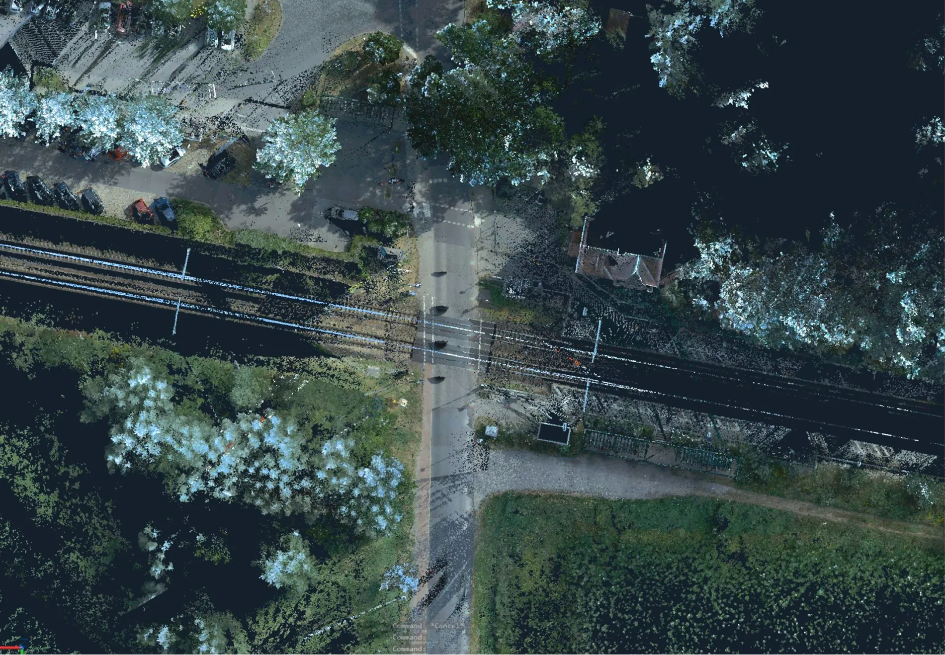
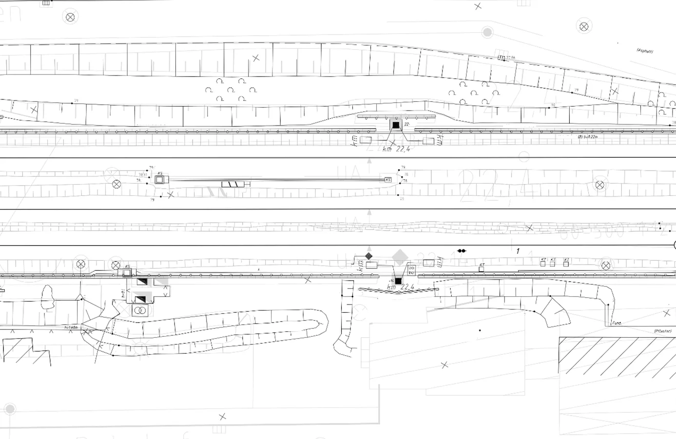
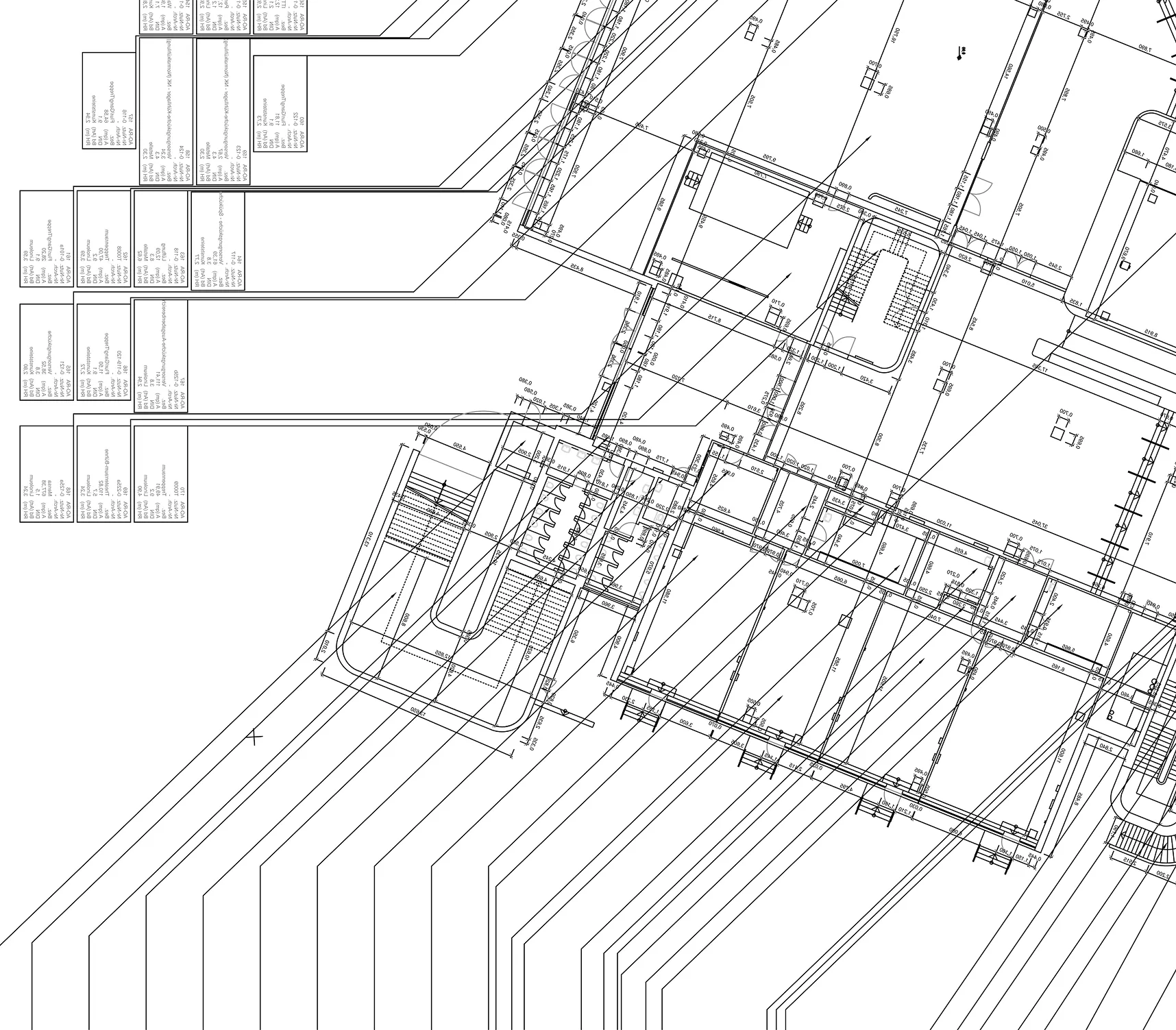
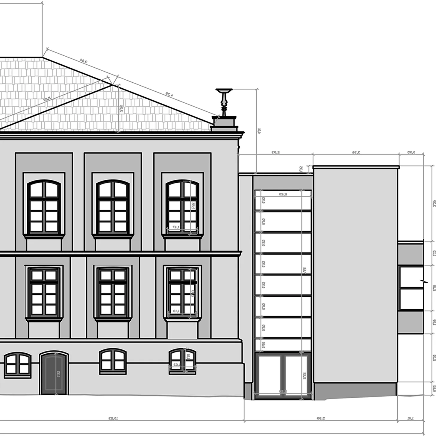
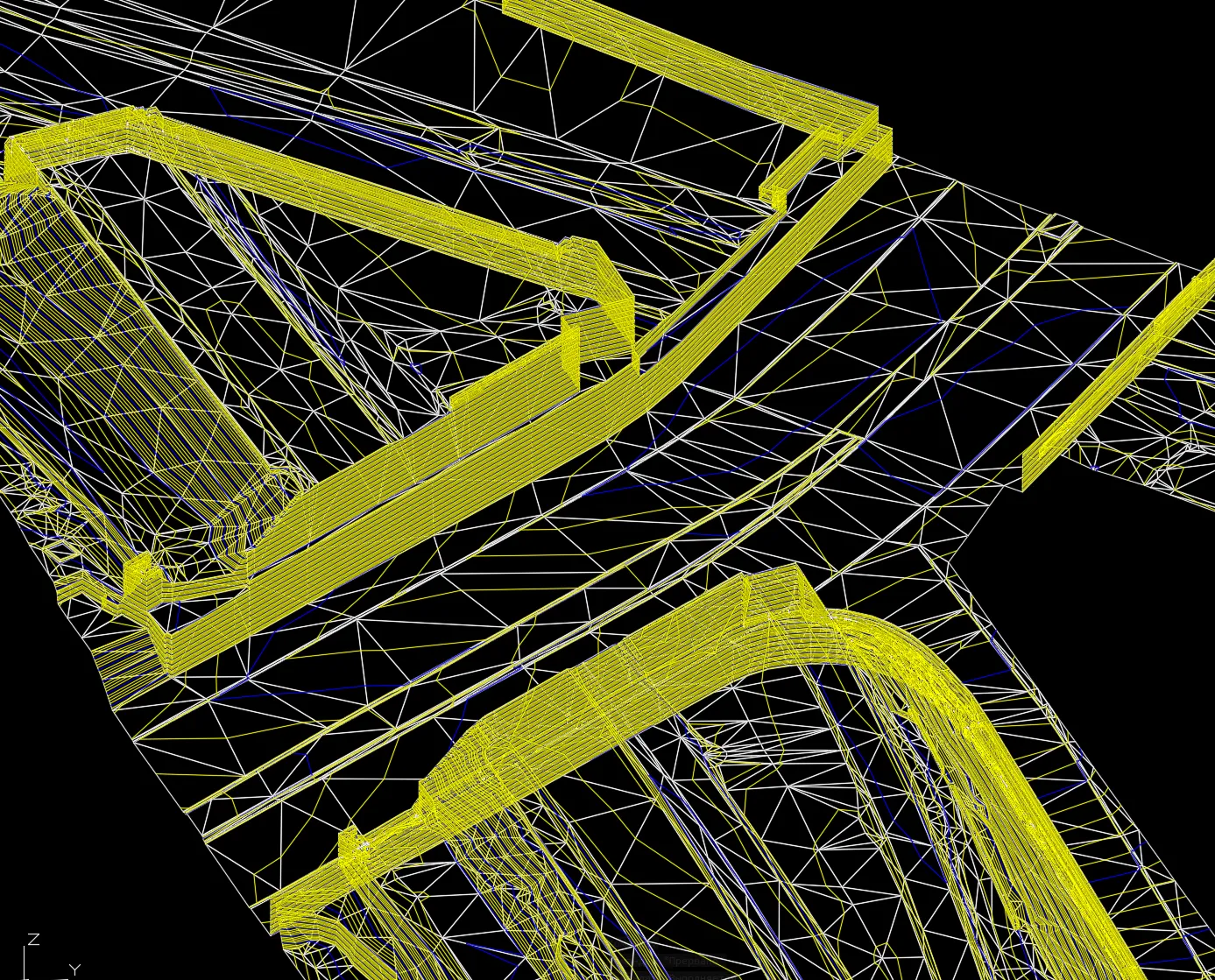
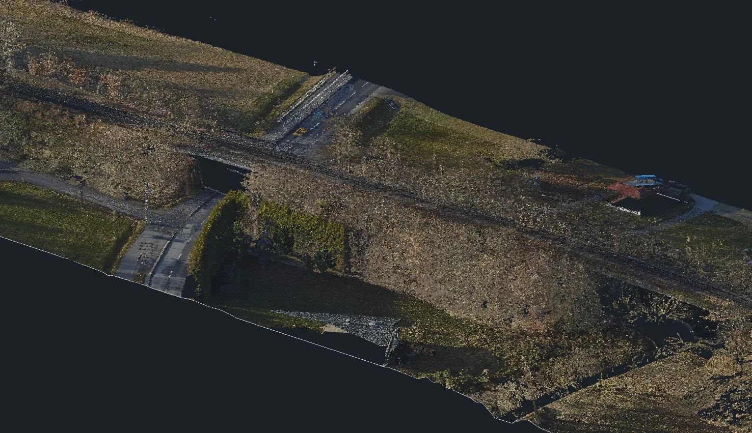
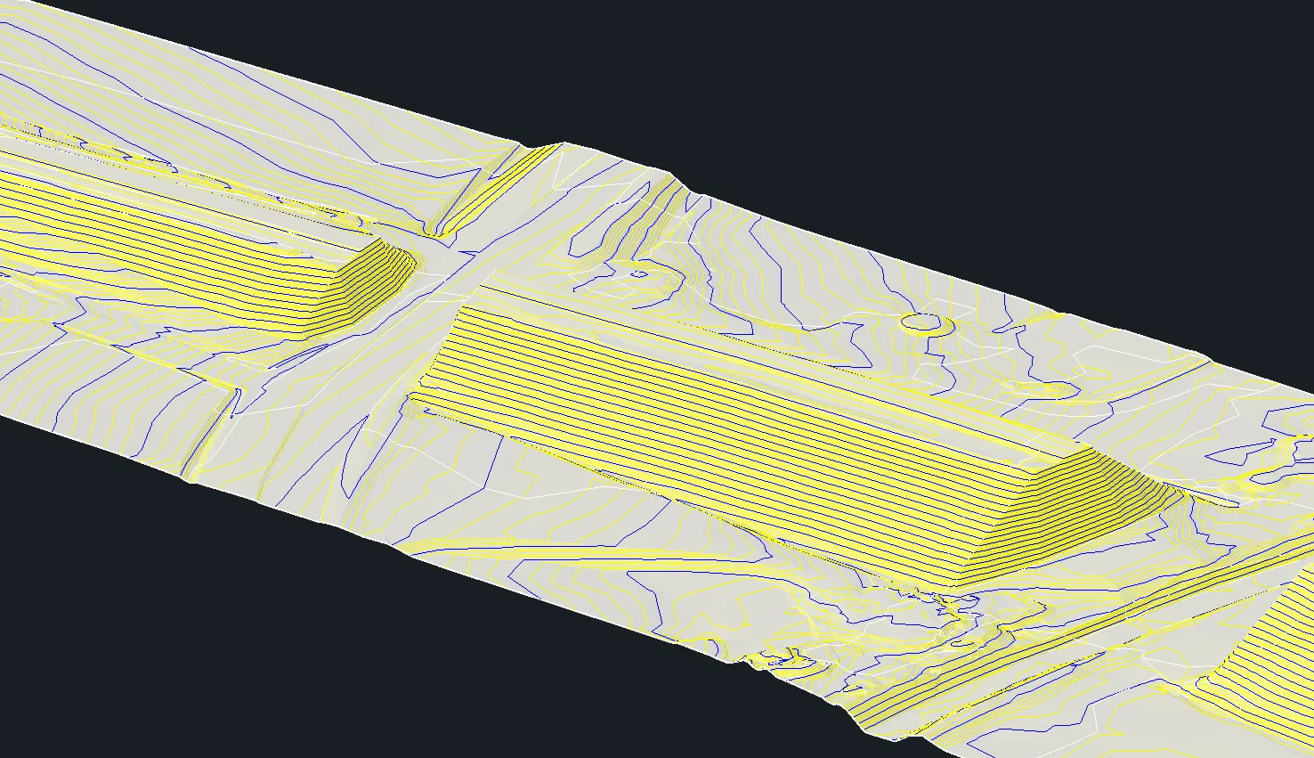
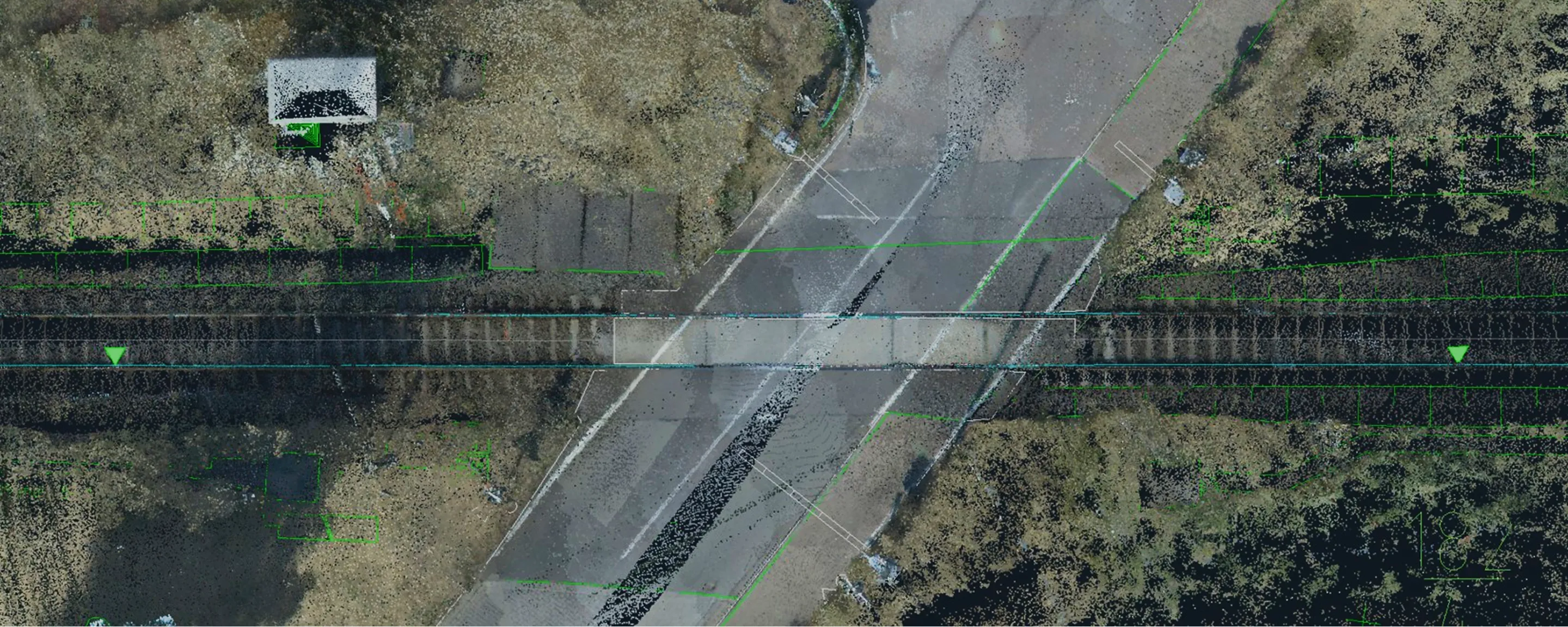
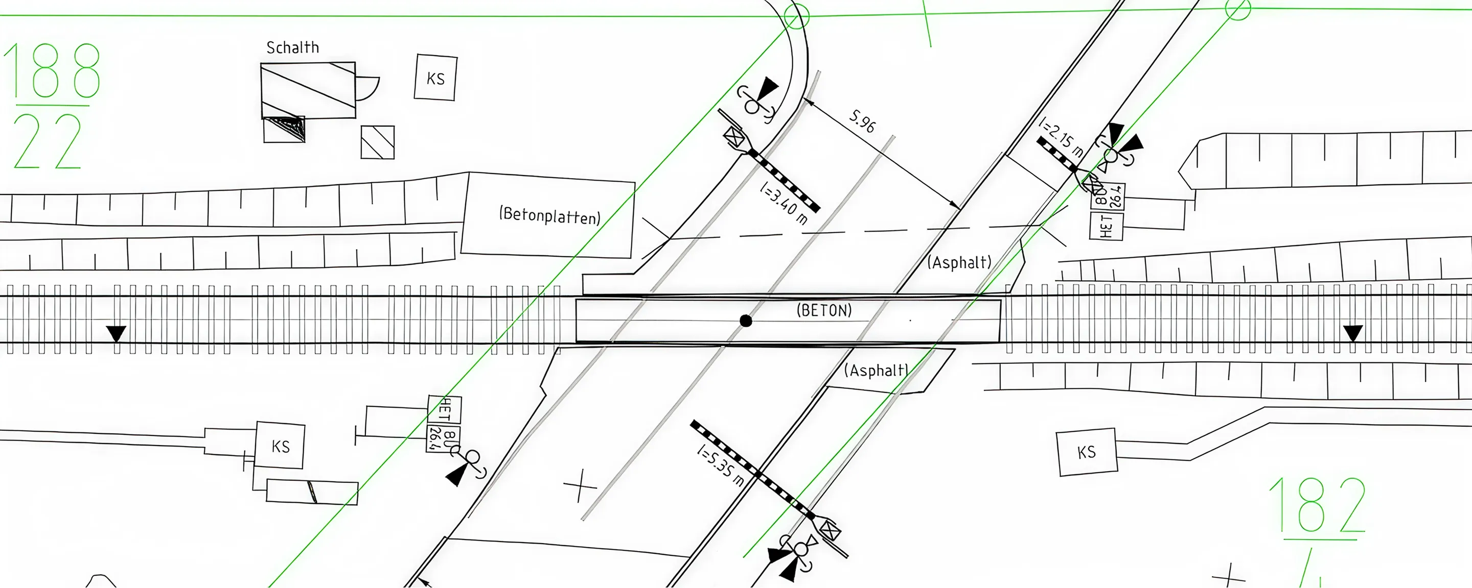
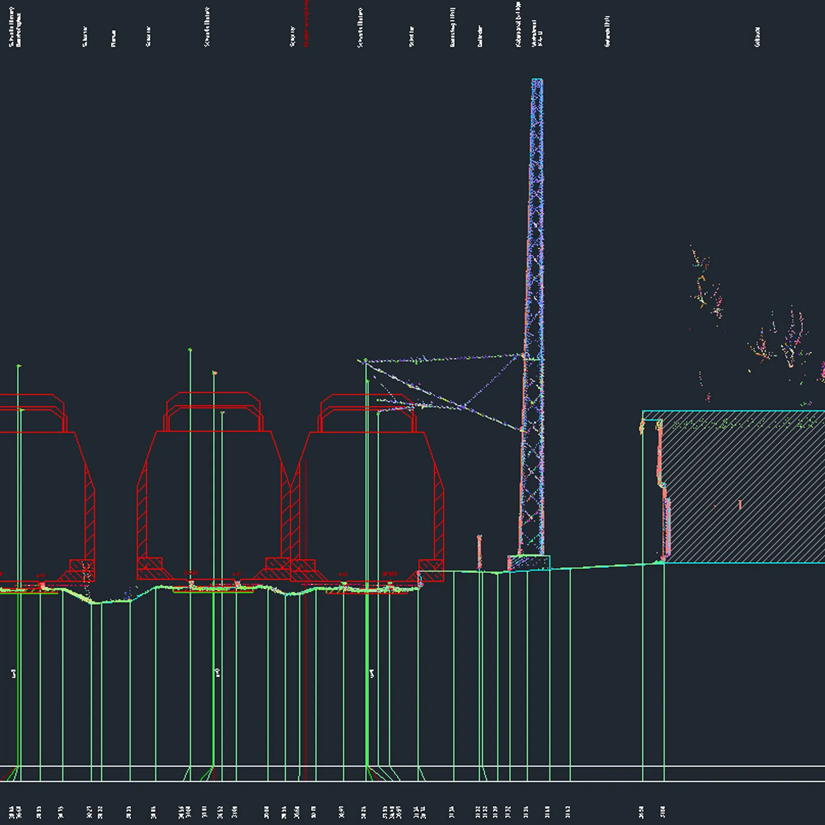
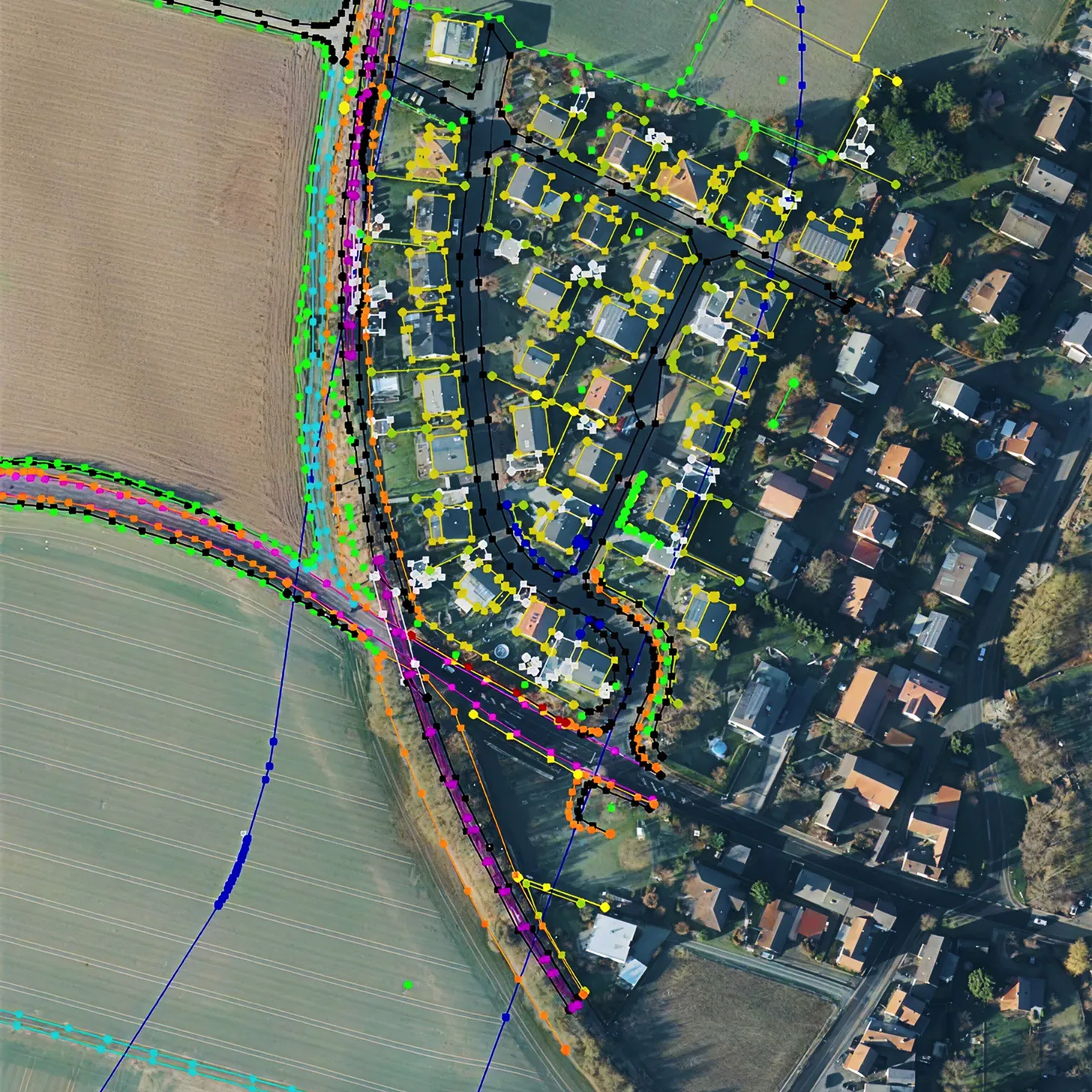
Stereo Analysis is a high-precision method of manual 3D interpretation and feature digitizing based on aerial photogrammetric stereopairs. The workflow enables reconstruction of the spatial position and shape of objects with photogrammetric accuracy, producing detailed vector datasets, digital terrain models, and precise geometric parameters.

This method is a standard in domains where spatial accuracy is critical: land cadastre, urban planning, territorial monitoring, infrastructure inventory, and the creation of a topographic/cartographic baseline.

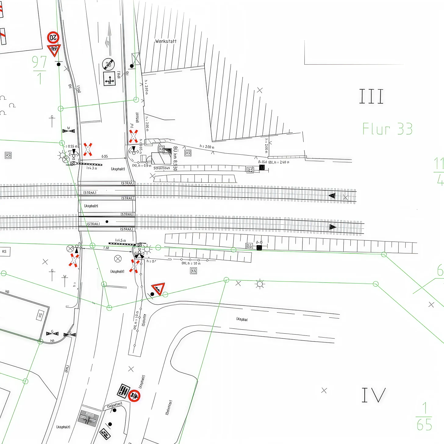
Performing the work in specialized professional environments (e.g., Summit Evolution or Digitals) ensures maximum detail, accuracy, and ergonomics of the digitizing process by providing a full stereoscopic effect. Output vector data are clearly structured and referenced to the coordinate reference system, enabling direct use in GIS, CAD, and BIM systems (e.g., .dxf, .dwg, .shp) without additional conversion or correction.

Execution Stages:

Technical Specification Alignment

Definition of the feature types for stereo analysis, scale, area of interest boundaries, required level of detail, coordinate reference system, and output formats.
01

Preliminary Data Analysis

Receipt of stereopairs from the client with exterior orientation parameters and camera calibration data, or (if required) preparation of the stereopairs by our team.
02

Working Environment Setup

Stereopair calibration/verification, image loading, and software interface configuration to ensure an accurate and ergonomic 3D interpretation workflow.
03

Stereo Digitizing (Vectorization in Stereo Mode)

Manual interpretation and digitizing of terrain, built-up areas, infrastructure, and outlines with direct measurement of elevations and 3D coordinates.
04

Attribute Data Population and Quality Control

Assignment of attributes to vector features as per the technical specification, followed by systematic checks of topology, integrity, and spatial accuracy of the resulting vector layer.
05

Final Export and Delivery to Client

Export of the finalized vector dataset to the agreed formats (.dxf, .dwg, .shp, .gml, .kml, etc.) and delivery to the client.
06

Free data audit and calculation — within 24 hours.

Submit your request

Our specialists will conduct a free analysis of your source data and provide a detailed proposal with cost and timelines within one business day.
Grazie! Your submission has been received!
We have received your request and will contact you shortly
Oops! Something went wrong. Please try again.
0
%